
Ultrasonic Welding Leaks in Medical Plastic Parts
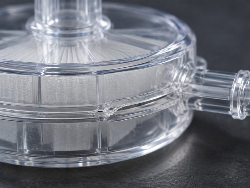
A medical filter housing can look fully welded and still fail a leak test. The seam may be smooth, with no visible gap. Yet a small unwelded section can leave a path for air or liquid.
When ultrasonic welding leaks occur, check the test setup, molded parts, joint design and tooling before changing the recipe. Then compare weld records with actual seal test results. This guide explains that sequence and includes a clearly labeled example using simulated trial data.
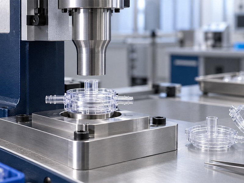
Why a strong looking weld can still leak
A joint can hold the two halves together without sealing the full perimeter. Uneven melting, dimensional variation or poor part support can leave a local leak path. Increasing weld time may add flash or damage a thin wall while the original problem remains.
Review the material grade, additives, molding conditions and joint dimensions together. Parts made from the same base polymer can behave differently when these details change. Dukane discusses these interactions in its medical ultrasonic weld failure guide.
Start with the test setup and the molded parts
Confirm that the leakage comes from the assembly. Worn port seals or leaking test connections can produce a failure even when the weld is sound. Check a known tight reference and a suitable leak standard before investigating the welding machine.
Next, compare passing and failing parts by resin lot, mold cavity and measured dimensions. Look for warped flanges, inconsistent joint features and contamination. Follow the resin supplier’s drying and handling instructions where applicable.
What you observe | What to check next |
Leakage near the same point on the seam | Joint continuity, local warpage and support beneath that area |
Failures concentrated in one mold cavity | Cavity dimensions, alignment and molded joint features |
Flash increases but leaks remain | Whether extra travel is damaging the joint or hiding poor support |
Results change with test delay | Part temperature, stabilization time and fixture sealing |
Failures after conditioning | Material compatibility with the specified aging or sterilization exposure |
Match the joint and tooling to the seal
The joint needs a continuous sealing path. An energy director concentrates heating at the interface. A shear joint uses controlled interference and travel to develop the bond. Geometry and material determine which design is appropriate. For the basic design principles, see our guide to energy directors in ultrasonic welding.
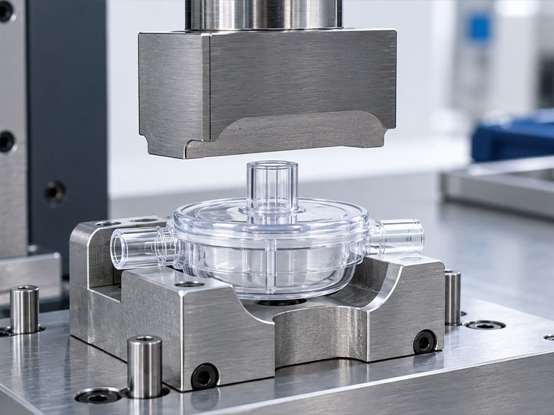
The horn and nest also need to match the part. Support the lower component near the weld, control alignment and avoid rocking under load. A nest that locates a part accurately may still provide insufficient support during welding. Check for marks, distortion and damage to internal features after each trial.
Use weld data together with leak testing
Record the recipe, actual weld time, energy, power and displacement where the equipment supports them. Link those records to individual sample IDs and leak test results. Process limits should come from trials that include acceptable and unacceptable parts.
A weld curve can help identify an unusual cycle. It does not directly prove seal integrity. Compare the available monitoring and control options in our ultrasonic plastic welding machines, including the 2000iQ series, against your application requirements.
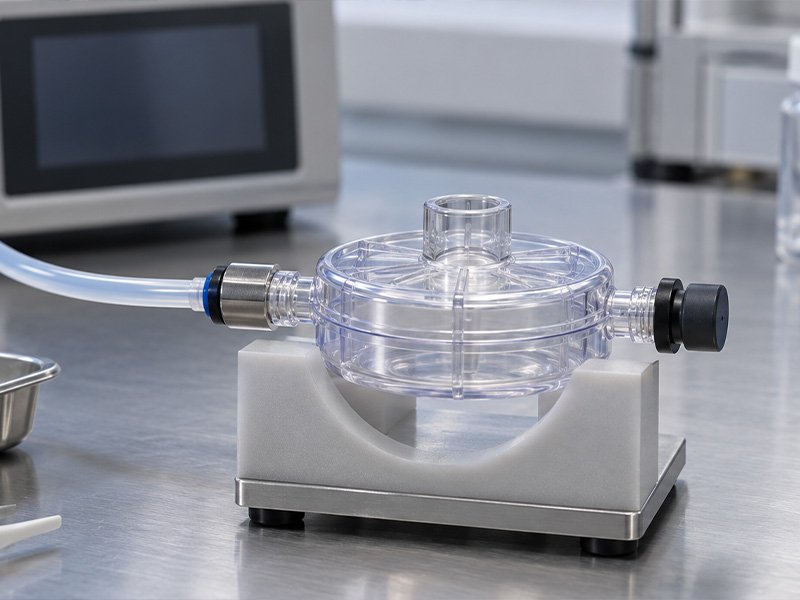
For a suitable rigid assembly, pressure decay testing pressurizes the part, allows stabilization, isolates the supply and measures pressure loss over a defined interval. Temperature changes and changes in test volume can affect the result. Keep the test circuit and timing controlled. Cincinnati Test Systems explains these factors in its pressure decay testing overview.
Define the test pressure, medium, measurement time and acceptance criterion for the actual device. Air leakage, liquid containment and microbial barrier performance are different claims. One test result does not establish all three.
Illustrative trial on a plastic filter housing
Illustrative engineering example with simulated data. This is a fictional development exercise, not a Hyusonic customer project or laboratory test report. All dimensions, settings and results below are invented to explain the workflow.
Consider two clear, unfilled polycarbonate housing halves with a 32 mm circular weld interface and a continuous shear joint. The same specified resin grade and molding lot are assumed throughout. The exercise evaluates the housing seam only, before membrane installation. It does not assess filtration performance or membrane sealing.
Thirty unique assemblies are assigned to three groups of ten. Each group uses the same mix of mold cavities. All parts are assumed to have been handled according to the resin supplier’s instructions. No clinical use or release decision is involved.
Example condition | Hypothetical setting or assumption |
Welding system | 35 kHz development press with collapse distance control |
Horn face amplitude | 20 micrometers peak to peak; not a generator percentage |
Trigger and weld force | 150 N trigger; 300 N weld force |
Hold after vibration | 0.40 s under force |
Target collapse | Groups A and B: 0.20 mm; group C: 0.25 mm |
Part and test environment | Equilibrated to 23 ± 2 °C before testing |
Pressure decay setup | Dry air at +50 kPa gauge; total connected gas volume 20 mL |
Example test timing | 2 s fill; 5 s stabilization; 5 s measurement |
Example screening rule | Pressure loss no greater than 100 Pa during the 5 s measurement |
These are demonstration values, not recommended production settings or industry acceptance limits. A real protocol must justify pressure and allowable leakage against the product specification. It must establish that part deformation, temperature drift and measurement uncertainty are adequately controlled. A preset stabilization time alone does not establish this.
For this fictional exercise, assume the test method has adequate repeatability and sensitivity around the screening limit. Checks with a tight reference and traceable leak standard bracket each group. The port fixtures seal only the ports; they do not bridge, compress or temporarily seal the housing seam. Samples are tested once under the same procedure.
Group A uses the initial nest. Group B adds uniform support beneath the weld region while keeping the recipe unchanged. Group C retains that support and increases the target collapse from 0.20 to 0.25 mm. The example tests two specific hypotheses in sequence; it is not a designed experiment or a validated optimization.
Simulated pressure decay results under the example screening rule
Group | Change evaluated | Simulated pressure loss | Within rule |
A | Initial nest; 0.20 mm collapse | 34–210 Pa over 5 s | 7 of 10 |
B | Improved support; 0.20 mm collapse | 27–140 Pa over 5 s | 9 of 10 |
C | Improved support; 0.25 mm collapse | 20–67 Pa over 5 s | 10 of 10 |
The invented results illustrate how a team might investigate support first, then travel. They do not demonstrate a real improvement or prove either change caused the difference. In a real study, repeat the comparison, account for run order and part variation, and inspect for flash, cracking and damage before selecting a recipe.
Even an actual result of 10 passing samples out of 10 would provide only limited trial evidence. It would not establish a guaranteed yield, long term capability or completion of process validation. Here, because the data are simulated, they establish no equipment performance at all.
Set acceptance criteria before production validation
ISO 13485:2016 provides a medical device quality management framework. It does not provide a universal ultrasonic welding recipe or a single leak limit for all medical plastic parts. Define requirements through the device manufacturer’s design and quality processes.
ASTM E2930-26 describes a pressure decay leak test method for vessels under positive pressure difference and excludes deformable vessels. Assess its applicability to the actual housing. The example above is a pressure loss screening illustration, not a claim that a complete ASTM procedure was performed.
A production program should address installation qualification (IQ), operational qualification (OQ) and performance qualification (PQ). The GHTF process validation guidance hosted by IMDRF explains these stages. Plan sample sizes and acceptance rules from risk and statistical objectives. Include relevant resin lots, mold cavities, operators and production shifts. Where required by the device design, evaluate the effects of aging and sterilization, and perform separate strength and functional tests.
Keep sample identification, instrument status, fixture revision, recipe revision, individual readings and failure investigations in the report. Review changes to resin, tooling or recipes through the quality system. A trial summary is useful only when the underlying records support it.
Questions buyers often ask
Can a normal weld curve replace a leak test?
No. Monitoring helps control the joining process. The product specification and validated inspection strategy determine which seal checks are required.
Will increasing weld time fix a leaking joint?
It may help an underwelded joint, but it can also increase flash or damage. Check the leak location, dimensions and support before adjusting the recipe.
Is there a standard leak limit for every medical filter housing?
No single value applies to every design. Specify intended use, pressure, test medium, method and acceptance criteria for the particular product.
Request a sample welding evaluation
Planning a new assembly or investigating inconsistent seals? Explore Hyusonic’s medical ultrasonic welding applications and send our team your part information for review.
Include the 2D or 3D drawing, resin grade, joint details, mold cavity information, sample quantity, target cycle time and sealing requirements. If parts already fail, include the test method, pressure, timing and individual results. This helps us discuss a suitable horn, fixture and machine configuration.
Request an application review and sample welding evaluation.