
How to Ultrasonically Weld Glass-Fiber Reinforced Plastics (PA66+30%GF) Without Cracking
Publish Data:2026.5.25 Author: Hyusonic
In modern automotive design, aerospace engineering, and industrial manufacturing, high-performance thermoplastics like Polyamide 66 with 30% Glass Fiber reinforcement (PA66 GF30) have become indispensable. From intake manifolds and water pump impellers to complex automotive sensor housings and heavy-duty gears, this composite material delivers exceptional tensile strength, dimensional stability, and thermal resistance.
However, the very additives that make PA66 GF30 mechanically superior also make it highly challenging to weld.
Manufacturing engineers frequently encounter two critical, margin-eroding failure modes during assembly: incomplete molecular fusion (resulting in low-strength, brittle joints) and vibration-induced micro-cracking at the joint interface or near delicate sensor elements.
To solve these assembly issues, you must understand the underlying thermodynamics of high-frequency vibrational heating in composite matrices. By pairing this knowledge with rigorous acoustic tooling calibration and advanced process control, you can achieve zero-defect production cycles. This engineering guide breaks down the precise steps to successfully weld glass-fiber-reinforced plastics without compromising structural integrity.
The Thermodynamics of Joining Glass-Filled Composites
To weld any thermoplastic, high-frequency mechanical vibrations must convert into localized frictional and viscoelastic heat. The localized heat generation rate, represented by the volumetric energy dissipation rate (Q), is governed by the following physical equation:
Q = 0.5 × ω × E'' × ε₀²
Where:
Q is the volumetric heat generation rate (W/m³).
ω is the angular frequency of the vibration, defined as:
ω = 2 × π × f(where f is the machine operating frequency, typically 20 kHz to 40 kHz).E” is the loss modulus of the thermoplastic matrix, representing its viscous, heat-generating capacity.
ε₀ is the dynamic mechanical strain amplitude delivered to the joint line.
When glass fibers (GF) are introduced into the polyamide matrix, they act as both thermal and physical barriers. Glass fibers increase the structural stiffness (elastic storage modulus, E’) but damp the viscous polymer response (E”). Because the glass fibers do not melt at the temperatures required to fuse nylon (PA66 melts at approximately 260°C, while glass fibers require above 1200°C), they act as physical obstacles to polymer chain entanglement.
If the delivered amplitude (ε₀) is too low, the polymer matrix fails to reach its melting temperature. Conversely, if you attempt to force melting by applying excessive static force or prolonged weld cycles, the abrasive glass fibers accumulate at the interface, causing localized stress concentrations. Under high-frequency cyclic loading, this stress concentration triggers micro-cracking.
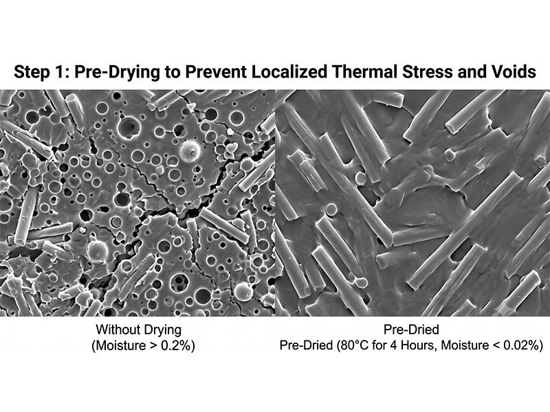
Step 1: Pre-Drying to Prevent Localized Thermal Stress and Voids
Polyamides are highly polar, hygroscopic polymers. The amide linkages within the PA66 backbone readily form hydrogen bonds with atmospheric moisture. At room temperature, standard PA66 can absorb up to 2.5% of its weight in moisture.
During the ultrasonic weld cycle, temperatures at the joint interface rapidly spike to over 280°C in fractions of a second. If the raw plastic components are welded in a “wet” state, this trapped moisture instantly vaporizes. The expanding steam forms micro-voids, blisters, and structural pockets inside the weld seam. These voids severely reduce the effective load-bearing area of the joint and serve as crack propagation points under mechanical stress.
The Engineering Protocol:
Drying Temperature: Pre-dry your PA66 GF30 components in a desiccant dryer at 80°C (176°F).
Duration: Maintain this temperature for a minimum of 4 hours.
Target Moisture Content: The moisture level must be brought below 0.02% by weight prior to placing the parts in the fixture.
By eliminating trapped moisture, you prevent steam expansion, lower residual molding stresses, and establish a solid, non-porous molecular bond.
Step 2: Choosing the Right Acoustic Tooling: HRC 45+ Hardened Titanium Horns
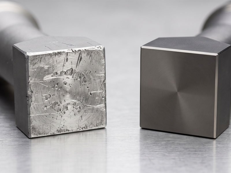
In ultrasonic welding, the sonotrode (welding horn) applies mechanical vibrations directly to the plastic component. Standard industrial horns are machined from aircraft-grade aluminum (Duralumin 7075-T6). While aluminum has excellent acoustic conductivity, its surface hardness is insufficient to withstand the abrasive nature of glass-fiber-reinforced composites.
Under continuous production, the exposed glass fibers at the part-to-horn interface will rapidly score, erode, and wear down an aluminum horn. This wear alters the resonant frequency of the acoustic stack, causes frequency drift, and introduces uneven pressure distribution, leading to localized part cracking.
The Engineering Protocol:
Material Selection: Always specify custom-designed Titanium alloy (Ti-6Al-4V) horns for composites with over 10% glass-fiber loading.
Surface Hardening: Ensure the titanium horn is vacuum-heat-treated and surface-hardened to a Rockwell hardness of HRC 45+.
Horn Maintenance: Annually inspect your titanium acoustic tooling for microscopic fatigue cracks and frequency deviations exceeding ±50 Hz.
Using hardened titanium tooling preserves the face profile of the horn, ensuring uniform pressure distribution across the component and preventing local stress concentrations that cause surface cracking.
Step 3: Amplitude and Booster Calibration: Tuning for Maximum Joint Penetration
Because glass fibers dramatically increase the melt viscosity of the polymer matrix, high-filled composites require greater vibrational amplitude to initiate melting. Attempting to weld PA66 GF30 with the same amplitude used for unfilled PA66 will result in “cold joints,” where the weld interface is simply burnished rather than fused.
To deliver the high mechanical strain (ε₀) required to melt the viscous matrix, you must modify the amplitude gain of your acoustic stack using an appropriate booster.
Converter Output: A standard 20 kHz converter typically generates an output amplitude of approximately 15 to 20 microns (µm).
Booster Gain: Integrating a green or gold booster with a 2.5:1 gain ratio multiplies this output, delivering 37 to 50 microns (µm) of vibration amplitude directly to the horn face.
This high amplitude quickly overcomes the material’s viscoelastic resistance, initiating rapid intermolecular friction at the joint interface. This rapid energy delivery minimizes the overall duration of the weld cycle, protecting delicate internal electronics and preventing the part from absorbing excess energy that could lead to crack propagation.
Step 4: Process Control: Eliminating Stress with 0.5ms Closed-Loop Control
Many basic ultrasonic welders operate on a simple “weld-by-time” or open-loop pressure trigger mode. For sensitive engineering resins like PA66 GF30, this approach introduces too much process variance. Environmental fluctuations, minor dimensional tolerances in injection molding, and ambient moisture variations will cause inconsistent energy delivery, leading to over-welding, material degradation, and thermal stress cracks.
To prevent micro-cracking, you must utilize highly precise, closed-loop process control. Transitioning to advanced ultrasonic plastic welding machines—such as those equipped with Industry 4.0 data acquisition systems and real-time monitoring—allows you to weld by Energy or Collapse Distance rather than pure time.
By utilizing an intelligent digital ultrasonic generator with automated frequency tracking, the system instantly self-adjusts to impedance changes at the weld joint. High-end systems, like Hyusonic’s 2000iQ and X-Series, utilize proprietary SWIM™ (Smart Welding Integrity Monitoring) algorithms.
Featuring an industry-leading 0.5ms closed-loop data acquisition rate, SWIM™ monitors the velocity of the horn’s downward travel. The moment the material reaches its peak melt state—detected via a change in mechanical resistance—the system terminates the ultrasonic energy. This prevents over-welding and stops high-frequency vibrations from stressing the solidified plastic, eliminating micro-cracking.
Industrial Troubleshooting Reference Matrix
When optimizing your PA66 GF30 assembly line, use this quick reference guide to troubleshoot and eliminate weld defects:
| Defect Identifier | Root Cause Analysis | Parameter Adjustment Strategy | Hardware Corrective Action |
| Micro-cracking near weld zone | Excessive high-frequency energy exposure, or moisture-induced steam pocket stress. | Reduce weld time; switch to energy mode; pre-dry parts at 80°C for 4 hours. | Install a 2.5:1 booster to decrease overall weld cycle time. |
| Incomplete joint fusion | Low amplitude, or glass fibers blocking polymer chain entanglement. | Increase amplitude; optimize joint design using a shear joint or deeper energy director. | Upgrade tool from aluminum to an HRC 45+ hardened titanium horn. |
| Surface burn marks or flash | Excessive downward force, or misalignment between horn and part. | Decrease trigger force; reduce hold pressure; ensure uniform nesting support. | Re-align fixtures to match ISO 9001 certified manufacturer standards for precision assembly. |
Summary of Joining Guidelines for PA66 GF30
Material Preparation: Dry at 80°C for 4 hours to lower moisture levels below 0.02%.
Ultrasonic Stack Frequency: 20 kHz is recommended for large parts; 30 kHz to 40 kHz is optimal for small, delicate sensors.
Acoustic Stack Selection: Combine an HRC 45+ titanium horn with a 2.5:1 booster.
Weld Trigger Mode: Use energy-based triggering or collapse distance control down to 0.01 mm.
By applying these rigorous, physics-backed parameters to your production line, you can eliminate structural cracks, increase pull-off strength, and achieve clean, repeatable welds for your glass-fiber-reinforced assemblies.
Partner with Hyusonic for Advanced Engineering Solutions
At Hyusonic, we leverage over 16 years of direct-factory experience and German technical cooperation to resolve the most challenging B2B welding bottlenecks. As a professional, ISO 9001 certified manufacturer, our standard machines deliver within 1 month, while customized automated systems are delivered in 1 to 3 months.
Ready to eliminate cracks in your production line? Contact our engineering team at rui.zhang@hyusonics.com or Request a Free Welding and Materials Test to optimize your assembly process.