Ultrasonic generator

An ultrasonic generator, also known as an ultrasonic power supply, is the core component of an ultrasonic welding system. Its primary function is to convert standard electrical energy (AC power) into a high-frequency electrical signal—typically ranging from 20kHz to 40kHz. This high-frequency signal drives the ultrasonic transducer, which in turn creates mechanical vibrations used for welding, cutting, or cleaning applications.

The generator works in close coordination with the transducer and booster (amplitude transformer), ensuring optimal frequency matching and stable power output. Accurate tuning between these components is essential to achieve efficient ultrasonic energy transmission and consistent welding results.

Hyusonic ultrasonic generator standard type

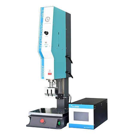
Ultrasonic Generator Standard Type

The standard ultrasonic generator with the latest China-made components ensures high conversion efficiency and stable output for 15- 40 kHz ultrasonic frequencies.

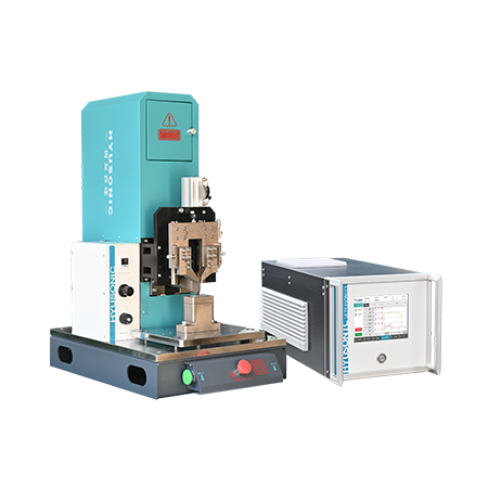
Ultrasonic Generator Intelligent Type

Intelligent ultrasonic generator with Germany-imported components delivers ultra-high conversion efficiency, stable 15–40kHz high-frequency output meeting international first-line standards.

Key Features of Our Ultrasonic Generators

Hyusonic offers advanced ultrasonic generators designed for high precision and industrial durability. Key features include:

  • Digital Control System: Intuitive interface for real-time parameter adjustments and precise power regulation.

  • Automatic Frequency Tracking: The generator automatically identifies and maintains the correct resonance frequency, ensuring stable performance even during load changes.

  • Constant Power Output: Maintains consistent welding quality across variable materials and conditions.

  • Overload and Overheat Protection: Built-in safety features extend equipment life and prevent failures.

  • Multi-Frequency Options: Supports 15kHz, 20kHz, 28kHz, 35kHz, and 40kHz configurations for various welding and cutting needs.

  • PLC & HMI Compatibility: Easily integrates with automated production lines via programmable logic controllers and human-machine interface (HMI) systems.

Applications in Ultrasonic Welding Systems

Our ultrasonic generators are widely used in a variety of industries that require fast, clean, and reliable plastic joining or cutting solutions. Key applications include:

ultrasonic plastic welding machine 8800st
Ultrasonic Plastic Welding
hyusonic IQ seriesultrasonic metal welding machine
Ultrasonic Metal Welding
ultrasonic blade cutting food
Ultrasonic Cutting

How to Match Your Generator to Transducers

  • Impedance Matching: ±10% tolerance recommended
  • Power Calculation: Transducer power (W) × 1.2 = Generator minimum rating

Analog vs Digital

Analog ultrasonic generators use analog circuits (e.g., potentiometers, amplifiers) for simple control of continuous signals, offering low precision (>±5%), basic functionality, and poor anti-interference, making them ideal for low-cost, basic devices. Digital generators, powered by microprocessors or DSPs, process signals digitally for high precision (<±1%), advanced features (e.g., display, storage), and strong anti-interference, but come at a higher cost and are suited for high-precision tasks like cleaning and welding.

The difference between digital and analog ultrasonic generators

Difference between Continuous and Pulse Modes

The distinction between continuous and pulse modes lies in the operating state of the ultrasonic signals output by the control box (i.e., whether the output is continuous).
The continuous mode continuously outputs energy, making it suitable for ultrasonic cleaning.
The pulse mode intermittently outputs ultrasonic signals, with energy concentrated at the moment of release. Its peak power is much higher than that of continuous output, and it facilitates heat dissipation, making it suitable for high-power scenarios involving precision parts or metal surfaces.

Customer FAQs

How to test ultrasonic generator output?

Frequency Check: Use an oscilloscope to measure output frequency (should match transducer rating, e.g., 20kHz ±0.5%).

Power Test: Connect a dummy load and measure RMS voltage/current (Power = V × A).

Amplitude Validation: Attach an amplitude gauge to the transducer horn (e.g., 50μm at 100% power).

Waveform Analysis: Ensure clean sine waves (THD <5%) via oscilloscope.

For safety, always disconnect power before adjustments.

Common materials:

  • Titanium (Ti-6Al-4V) – High strength, long lifespan

  • Aluminum 7075 – Lightweight, economical

  • Tool steel – For specialized metal welding

Causes include:
✖ Resonance mismatch (incorrect frequency tuning)
✖ Overheating (poor cooling or excessive amplitude)
✖ Material fatigue (low-grade titanium or aluminum)

Yes! Custom horns are CNC-machined to match:

  • Unique part shapes (e.g., medical device components)

  • Specific amplitude requirements

  • Machine compatibility (Branson, Herrmann, etc.)

Look for manufacturers offering:
✅ ISO 9001 certification
✅ Free CAD design support
✅ Frequency testing reports

Send your inquire now

Contact Form 1
滚动至顶部